Mercruiser Alpha One Trim Sender Wiring Diagram
Connected the trim sender wires from the lower unit to the brown/white and black wires which match the original wiring connections. 800 x 600 px, source:
Mercruiser Trim Sender Wiring Diagram Hanenhuusholli
Connect an ohmmeter to the switch bullet leads.

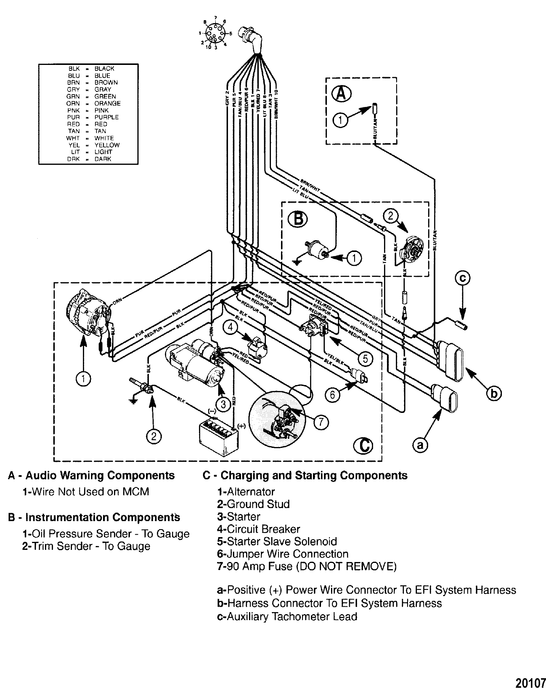
Mercruiser alpha one trim sender wiring diagram. 805320a1 trim sender and trim limit switch kit page 4 of 10 2. Mercruiser inboard engine ignition wiring diagram keywords: Blue oil pressure sender to gauge
Mercruiser power trim wiring schematic sterndrive and sender the switch 1981 outboard with tilt pump troubleshooting mercury diagram is question again cables. The trim limit switch is mounted to the port side of the gimbal ring. Each part should be placed and connected with different parts in specific way.
Mercruiser alpha one trim sender wiring diagram mercruiser trim sender wiring diagram. Behind that button is a bolt remove it and the handle will come off. Mercruiser trim pump wiring diagram another image.
The trim limit switch is mounted to the port side of the gimbal ring. Newer model switches will have a tl or trim limit embossed in the plastic (see image below) the trim sender switch is on the. A b disconnect trim limit switch wires at the power trim pump.
Mercruiser trim/tilt wiring for the position sender, the diagram shows one side to ground, and the other side to a brown/white wire, that goes to the connector, and on up to the trim gauge. Diy mercruiser alpha/bravo trim sender install under 30 minutes, not for new boat but easy if you have an older boat and don't want to spend a lot pulling ev. Mercruiser trim/tilt wiring for the position sender, the diagram shows one side to ground, and the other side to a brown/white wire, that goes to the connector, and on up to the trim gauge.
Additionally you can easily bookmark this post to you. You could acquire this amazing picture for your portable, mini netbook or pc. January 22, 2019 april 12, 2020 · wiring diagram by anna r.
Operate power trim and note meter reading. With such an illustrative guide, you will have the ability to. Alpha one outdrive trim wiring diagram schematic diagrams omc trim gauge wiring diagram mercruiser trim sender.
Wiring diagram contains several comprehensive illustrations that present the connection of varied items. Meter should show continuity with drive unit in down position. Disconnect the trim limit switch bullet leads from the trim control harness inside the boat (see figure 1or figure 3).
It contains instructions and diagrams for different varieties of wiring techniques and other things like lights, home windows, and so forth. Lower unit, cooling & transmission. 1979 70 hp mercury outboard tach wiring diagram circuit diagram.
Clean gimbal housing mounting flange with sandpaper and wipe clean with lacquer thinner. The trim sender switch is used to send a signal to the trim gauge so you can see the level of the drive. With such an illustrative guide, you will have the ability to troubleshoot, avoid, and full your projects with ease.
It contains instructions and diagrams for different varieties of wiring techniques and other things like lights, home windows, and so forth. Question, does the switch in question have a push feature? Wiring diagram contains several comprehensive illustrations that present the connection of varied items.
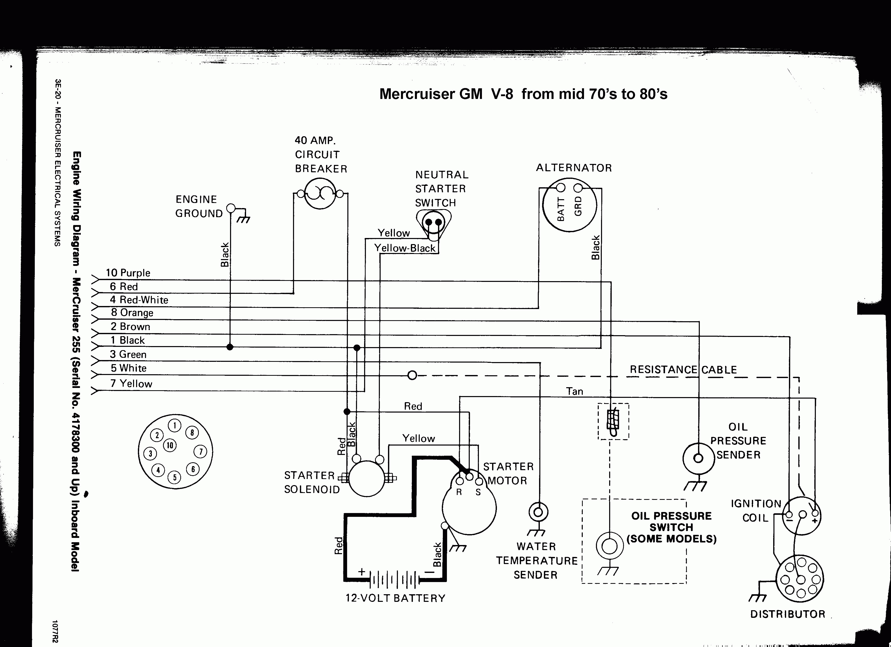
The one in the tech articles has a very low resolution and is hard to read the text. 3 0 mercruiser ignition coil wiring diagram by yahutt mang december 15 2018 1994 ford probe diagram wiring diagram1995 box mercruiser 3 0 diagram 1 smo zionsnowboards de u2022 rh electrical system wiring diagrams. Mercruiser trim sender wiring diagram.
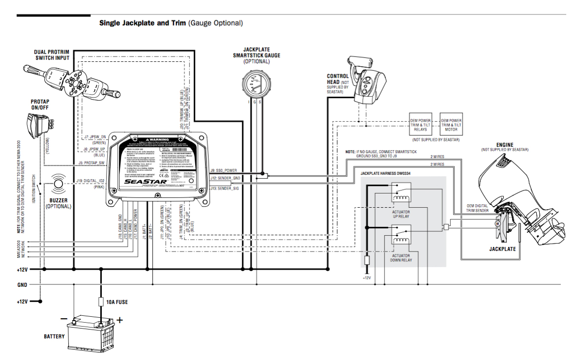
December 15, 2021 · wiring diagram. Mercruiser trim sender wiring diagram you will want an extensive professional and easy to know wiring diagram. Now, does anyone have the complete wiring diagram for the trim system.
Look on the back of the gauge and see if there is a br/w wire there. The trim senders are located on either side of the gimbal ring. Install trim position sender as follows:
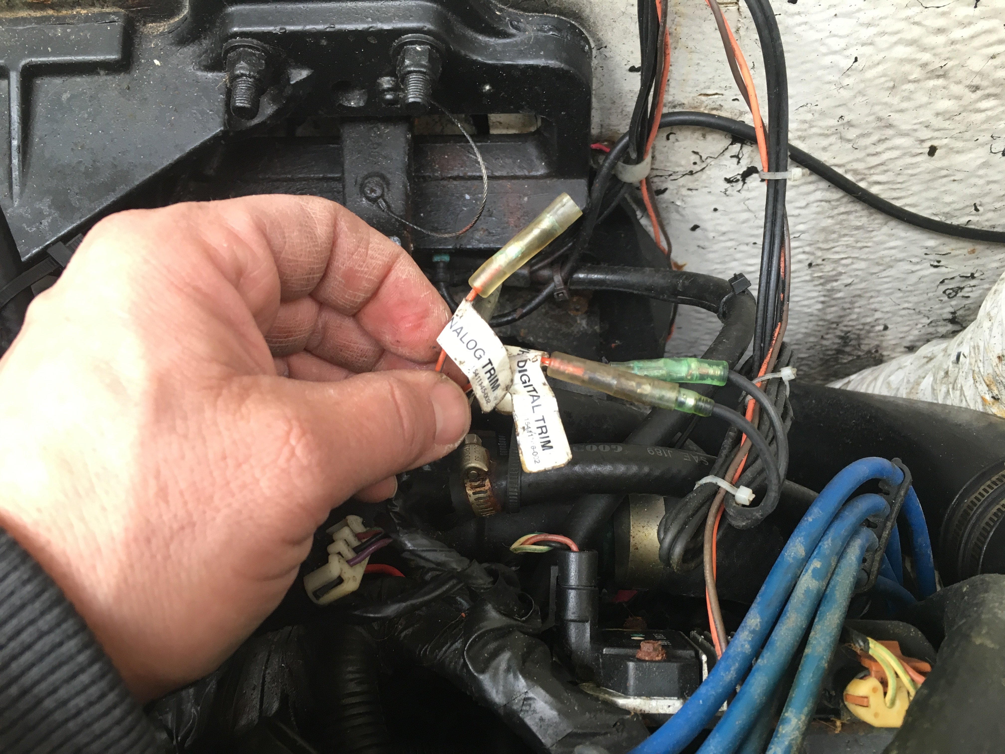
Place sterndrive unit in the full down/in position. Trim wiring alpha 1 ok, sounds like i will be replacing them both. Step by step instructions detailing how to remove a mercruiser bravo sterndrive to repalce the trim position sender and trim limit switches.
Mercruiser Trim Sender Wiring Diagram Wiring Diagram
25 Mercruiser Trim Sender Wiring Diagram Wire Diagram Source Information


My alpha 1 outdrive is stuck in the "up" position. the trailer button still energizes the trim

Alpha One Trim Sender Wiring Diagram

Mercruiser Trim Sender Wiring Diagram Diagram Resource Gallery
Mercruiser Trim Pump Troubleshooting Help The Hull Truth Boating and Fishing Forum
Mercury Alpha 1 Shift Interrupter Wiring Diagram
Mercruiser Trim Gauge Wiring Wiring Diagram

Mercruiser Trim Sender Wiring Diagram General Wiring Diagram

Mercruiser Trim Sender Wiring Diagram Hanenhuusholli
I have a Mercruiser Alpha 1 (1996). The "up" trim does NOT activate the pump. The "down" does


[RW_3625] Alpha One Mercruiser Engine Diagram Wiring Diagram
Alpha 1 Gen II trim indication wiring question Page 1 iboats Boating Forums 9999959

Mercruiser Trim Sender Wiring Diagram Drivenhelios

Mercruiser Trim Gauge Wiring Diagram Atkinsjewelry


Need wiring for 1987 4 cyl. power trim wiring
My alpha one gen 2 sterndrive does not work. I replaced the old trim buttom with a new (bought a

I have a 2004 Bayliner 175 BR with a 3L Alpha 1 Mercruiser, my trim will not lower or raise

[RW_3625] Alpha One Mercruiser Engine Diagram Wiring Diagram